24小时服务热线
021-31300595
来源:上海樊伊电子科技有限公司 发布:2018-01-14 20:48
In engineering, the term “isolation” has many meanings. In basic circuitry design, it refers to a topology where two subcircuits of the overall system are electrically separated with no “ohmic” or “galvanic” path between them (infinite resistance), yet signal, power, or both can still pass between those subcircuits.
A tangible example of isolation is the use of an electromechanical relay. The coil-drive circuit and the relay-contact circuit are completely isolated from each other. In fact, the voltage level, current rating, and signal on the coil can be completely different than the same parameters on the contact circuit, a characteristic which is often used to advantage in systems. For example, a 24VDC signal at a few tens of milliamps can control a high-voltage AC signal at many amps, with no electrical contact between the drive and the load. Of course, an electromechanical relay is not suitable for non-stop switching at tens of kHz, so all-electronic alternatives are needed.
Isolation can be for signals or power (both AC and DC). AC is the easiest to isolate, by simply using a traditional transformer. This is often done in AC/DC supplies, where a transformer can pass the line voltage to the system for rectification and regulation, yet there is no path from the system back to AC line or vice versa—thus avoiding ground-related shocks and other potential issues.
For DC power, the isolation situation is more difficult and usually requires chopping the DC to create an AC-like waveform, then using a transformer, and finally rectifying the secondary-side output; alternatively, a switched-capacitor topology can be used.
Isolating an information-bearing signal is a moredifficult challenge. For analog signals, various techniques include modulation of a higher-frequency carrier, then passing it through a transformer or a even a miniature wireless link; or first digitizing the analog signal and then converting it back to analog form. The latter approach is attractive because it is much easier to isolate a digital signal than an analog one, as we will see below as we look at isolation for the gate-drive signal of a motor’s power devices.
Isolating subsystems is recommended for several reasons. First, it protects the user from a fault on the high-voltage side. For example, if an AC-powered load such as a motor accidentally shorts to the control electronics, the full line potential could reach the user panel and controls—obviously, a dangerous situation.
Second, it protects the electronics against such faults. Again, the high voltage which appears due to internal high-voltage short circuit would not have a path to “ripple back” into the low-voltage control electronics, as it would be blocked by the isolation barrier.
Third, unrelated to faults and failures, isolation is needed due the inherent nature of some common circuit topologies. In a simple example, consider measurement of the voltage across a battery at the top of series stack of hundreds of batteries, such as in an electric or hybrid vehicle. Although the battery itself has low, safe voltage across it, the battery is at several hundred volts above ground and, therefore, is at a high and dangerous potential. By isolating the battery measurement circuitry from ground, only the small voltage of the battery will be seen.
Finally, although isolation is often needed only on the high side, designers usually include it in on both high and low sides, for several reasons. In addition to affording safety, isolation also:
Many motors operate at high voltages, so there are immediate user safety and system fault-protection issues. However, isolation is needed because many motor-drive circuits need it to function properly. Consider the basic half-bridge or H-bridge design used for controlling a motor via MOSFETs (or IGBTs), as shown in Figure 1.
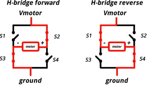
Figure 1: The classic H-bridge motor drive configuration shows how four controlled switches can be used to manage motor direction, as pairings of opposite switches are open and closed. (Source: blog.solutions-cubed.com)
In the bridge arrangement, gate drivers are positioned between the control electronics and the power devices. By turning the crosswise switching pairs of the upper/lower power devices on (and off), the motor is controlled to run forward or reverse. But also note that the upper-side power device cannot be connected to ground as it is connected between the supply rail and the motor as load. At the same time, the driving circuitry is ordinarily connected to ground, shorting out the upper-side device and rendering the circuit useless. The solution is to use isolation between the control electronics and the MOSFET (or IGBT) drivers. This isolation ensures that the signal that turns on the gate drivers—and thus the MOSFETs—has no path to ground, as shown in Figure 2.

Figure 2: The path between low-voltage control signal, to gate driver, to controlled power device (MOSFET or IBGT), and then to motor often needs galvanic isolation for both safety and circuit functionality.
Two approaches are commonly used for providing isolation for motor-gate drivers: Magnetic and optical. Both are conceptually simple but involve many subtleties in component choice and design-in techniques.
The magnetic approach uses a pulse transformer interposed between the control electronics and the gate-driver input. The signal that turns the gate driver on or off (and that turns the MOSFET on or off) goes through this transformer, which is inherently a non-grounded component. The transformer can be a discrete device or can be physically implemented as part of a hybrid-like IC (Figure 3), where integrates a planar pulse transformer into a single component in their ADuM Series.
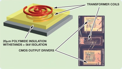
Figure 3: Magnetic isolation can use either discrete transformers, shown (left) schematically or (right) built as planar co-located coils in an IC-like package of the ADuM3223 and ADuM4223 construction. (Source: Analog Devices, Inc.)
The optical approach uses an optocoupler (also called an optoisolator) which combines an LED and phototransistor in a single package. The LED is driven by the control signal, converts the electrical input into photons, and channels these photons along a constrained optical path where they reach the phototransistor. That device reconverts the photons and signal they represent into an electrical signal, so the photonic path acts as the electrical isolation barrier. Both the input and output sides are relatively easy to interface with their associated circuitry, many are available with the same packaging as conventional ICs.
They can even be tailored to loads, such as the Avago ACPL-P341 and ACPL-W341 3A IGBT gate-drive optocoupler for IGBTs and MOSFETs (Figure 4). Its voltage and high peak-output current supplied by this optocoupler make it well-suited for direct driving of devices with ratings up to 1200V/100A.

Figure 4: The optoisolator is a widely used alterative to magnetic isolation, and it offers compact design and simple interfacing. (Source: Avago/Broadcom)
There are also isolation devices such as those in the family from based on capacitive coupling of a high-frequency signal within a CMOS IC (Figure 5). These offer many beneficial attributes, including operation into the 100Mbps range, but this speed is unneeded for motor control, which is usually in the tens-of-kHz zone. These isolating devices are providing an alternative to established magnetic and optical isolation approaches.
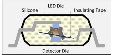
Figure 5: Capacitive coupling within an IC-like package of the Si828x series provides a newer isolation option, and it offers small size with high isolation voltage. (Source: Silicon Laboratories)
The obvious question is: Should this design use magnetic or optical coupling, or perhaps a newer technology? As in most engineering decisions, the answer is simple: It depends. Factors include maximum voltage rating, cost, product size, longevity, and regulatory requirements. For any general statement about attributes of each approach, there will usually be devices and examples that are exceptions to that statement. But among the relevant parameters are these considerations:
Maximum voltage and isolation rating: These are determined by both the underlying technology and device physics. All technologies are offered up to several thousand volts, but transformer isolators can be designed to go into the tens of kV range, if needed.
Performance needs: All types can provide performance which meets most basic requirements with respect to speed for motor-driver applications.
Performance needs
版权所有 Copyright(C)2009-2018 上海樊伊电子科技有限公司 沪ICP备16047676号